Recently, I've picked up a new hobby - DJing. I find it's a great way to enjoy music, and it's pretty fun to learn too.
I've got a great DJ controller, but I find it's missing a couple of buttons and knobs for extra functions - especially post effects which some other brands of controller do have. To fix that I've been wanting to make a small 'add-on' controller that has remappable buttons and knobs. I guess it's essentially a macro pad.
Design
For this project, I started out not really having much of a plan, but I knew I wanted to have a bunch of knobs (or potentiometers) to have analog control over effects, and a few buttons to turn effects on and off, or do other functions too. I decided that 6 potentiometers and 8 buttons would be plenty.
For the microcontroller, the brains behind the project, I went for a Seeed Studio XIAO RP2040. I liked the form factor of this from one of my previous projects and like the RP2040 in general. Although as you'll see below on the schematic, this microcontroller doesn't have many pins, but more on that later...
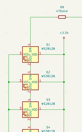
Then what is an electronics project without RGB lights? So I added WS2812 LEDs for each of the buttons which can show the status of each. These LEDs take in power and a single data line for controlling the colour. They daisy chain together, so you can have a big long line of LEDs that are individually addressable (i.e. you can change the colour of each individually), still with just one data line from the microcontroller. Pretty neat! I also added in a resistor for the power line, as it was suggested best practice on the datasheet, although it would still work fine without.
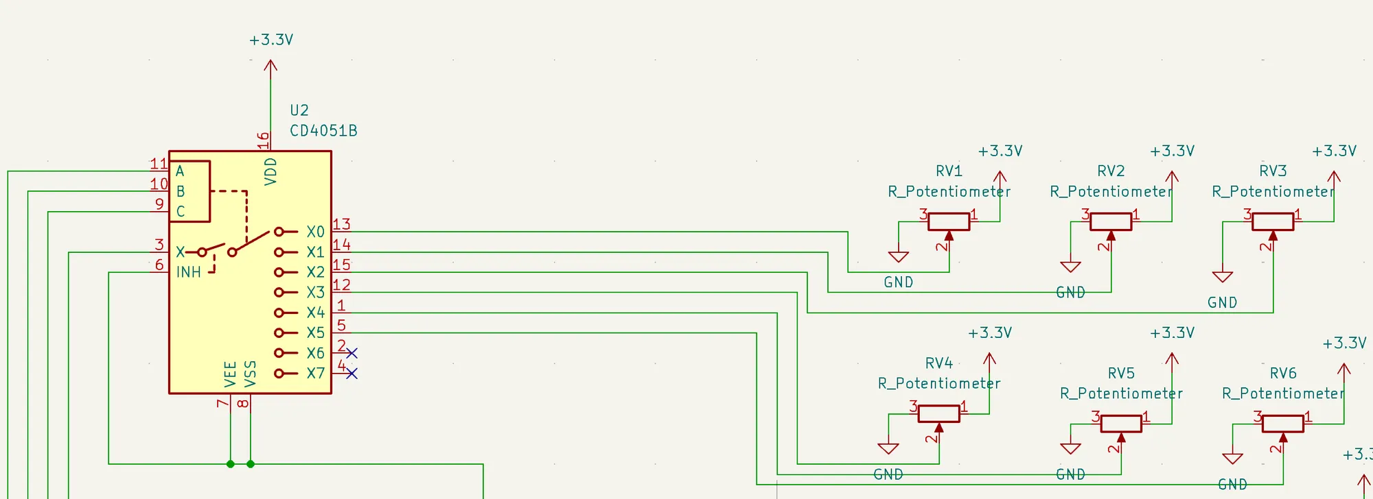
Back to the pins problem. I could have chosen a bigger microcontroller, but even with something a little bigger, I might have struggled for pins, with 14 being needed for all the inputs. After a bit of research, I found that using some multiplexers would help me out here. I'm glad I got to try them out because they're pretty cool. For the potentiometers, I used a CD4051B chip which uses 3 pins on the microcontroller to set an address. This address then sets which input is given to the microcontroller. So the 6 potentiometers are hooked up to the chip, and the chip only uses 4 pins on the microcontroller (although I could have had an extra 2).
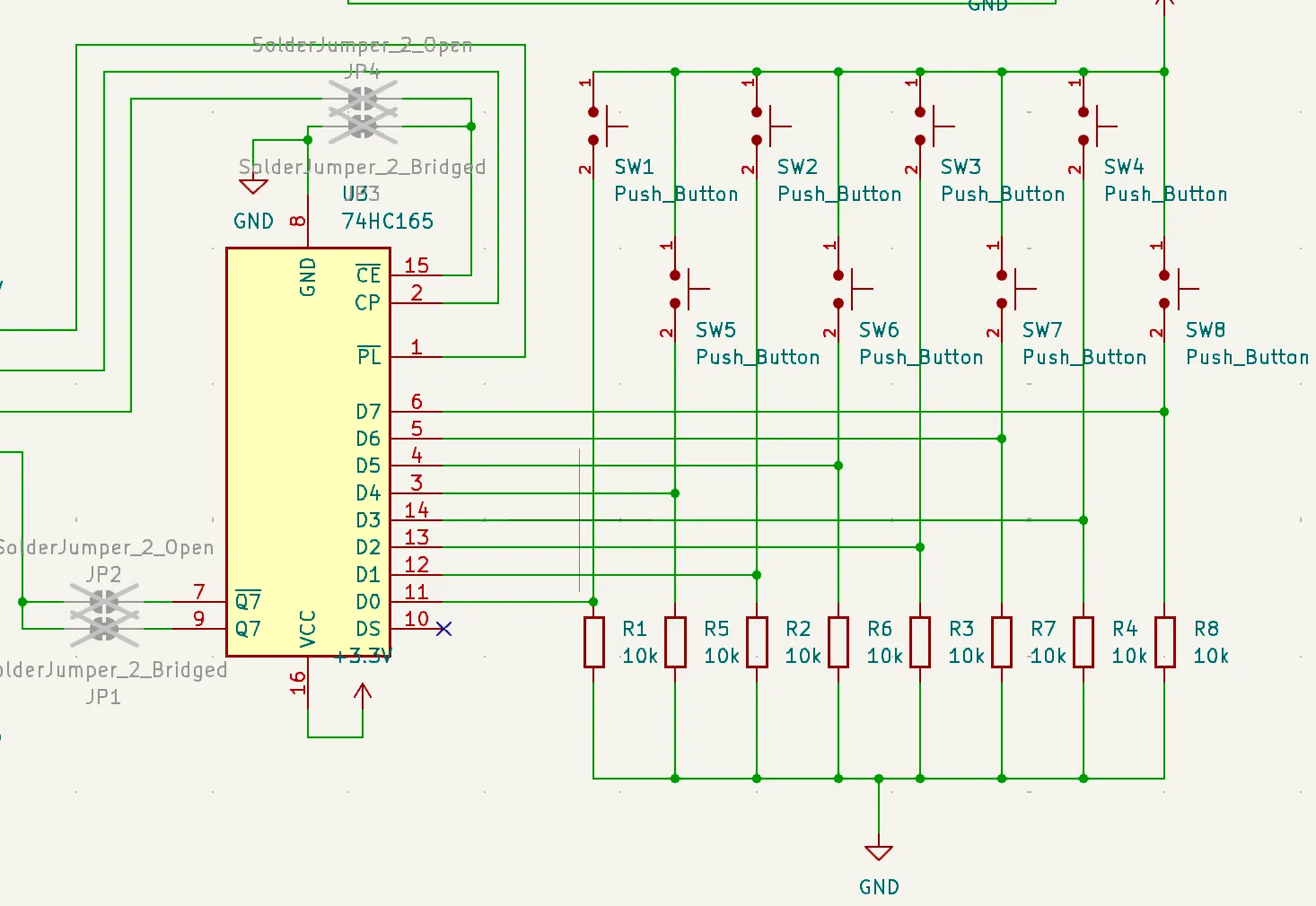
For the buttons, I used a 74HC165 shift register which takes the button inputs (in parallel) and sends them to the microcontroller over serial. This takes up only 3 extra pins on the microcontroller for the 8 inputs. When I was looking into using the shift register, I found some conflicting advice on how to hook it up, so I added in some jumpers that I could connect or disconnect later on if the way I had wired it up didn't work. (But spoiler alert, it was fine in the end).
For good measure and future-proofing, I also added in a Grove connector, which will let me plug in I2C devices. The idea being if I needed even more inputs, I could add another board that plugs in.
Here's my final schematic for all of that. It's a bit messy!

I would normally test on a breadboard at this stage to make sure I have all the connections right, and it would have meant avoiding adding the jumpers. However, I didn't have a lot of the parts on hand, so I took a risk and designed the PCB.
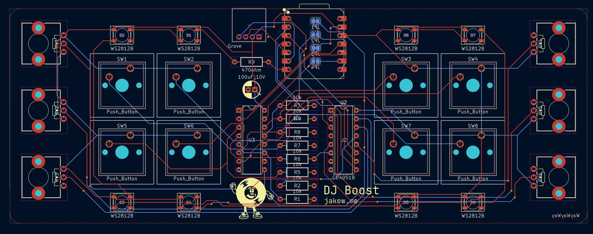
Some casual Friday night PCB designing 😎. This is the most complicated I've made for while so this routing is pretty tricky
— Jake Walker (@jakew.me) 2025-02-21T20:22:41.250Z
It took me a good few hours to get everything routed, and it was certainly one of the more complex boards I've designed for a while. But I didn't help myself by wanting to put the resistors all in a row in the middle and the two chips either side.
After having tried it out, I would have spaced or positioned the potentiometers differently to give a bit more room as they're a little cramped. Although I've got some ideas for 3D printed parts that may help.
If you want to make your own, below is a list of the parts I used as well as a download of the KiCad project, but if you check out my previous post on designing PCBs, you could make your own which is definitely the more fun route!
Parts List
Parts
- 8x WS2812 5050 SMD LEDs
- 1x 470Ω resistor
- 1x 100µF capacitor
- 1x CD4051BE Analog Multiplexer/Demultiplexer
- 1x 74HC165 Shift Register
- 6x potentiometers (RK0938N)
- 8x Cherry MX-style switches
- 8x 10k resistors
- Seeed Studio XIAO RP2040 Microcontroller
Getting the PCB
PCBWay kindly offered their support for this project by providing their PCB prototyping services. As I talked about in my previous post, the ordering process with PCBWay is really quick and easy, and is as simple as using their plugin in KiCad, or uploading the exported files.
Shortly after ordering, one of their engineers sent me a message, asking for clarification on some of the drill holes for the potentiometers. I think the footprint I used for them may have been a bit ambiguous, but I was able to clarify that the large holes were not electrical connections to the engineer. It was great to have an engineer check out the design and it could have potentially saved me from an irritating problem.
After ordering, I think the manufacturing process took a few days and on the PCBWay website, I was able to check what stage of manufacturing that the board was in. I always end up choosing the most economical shipping when getting PCBs as I'm never in a rush. So after it was complete the finished boards arrived in just under two weeks.
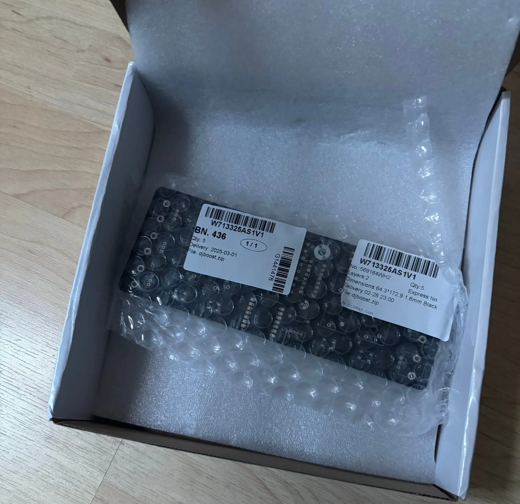
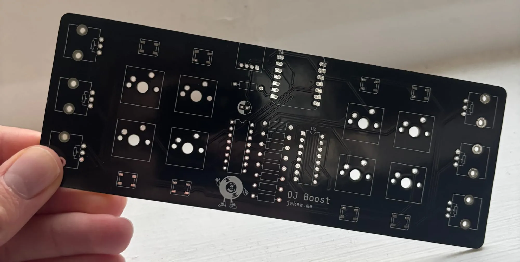
The boards arrived in a nicely packaged box and were protected in some bubble wrap packaging. The boards are great quality, the solder mask and finish of the board is really nice feeling and they were a joy to solder on.
Soldering Up
While I was waiting for the boards to arrive, I ordered up all the parts I needed. I found it particularly difficult finding the multiplexer and shift register chips somewhere where I didn't have to buy in bulk and wasn't crazy expensive for small orders. And I did even have to switch out a few of the components before ordering the PCB for these reasons.
After the parts arrived, I got to soldering on my not very safe cardboard work surface.
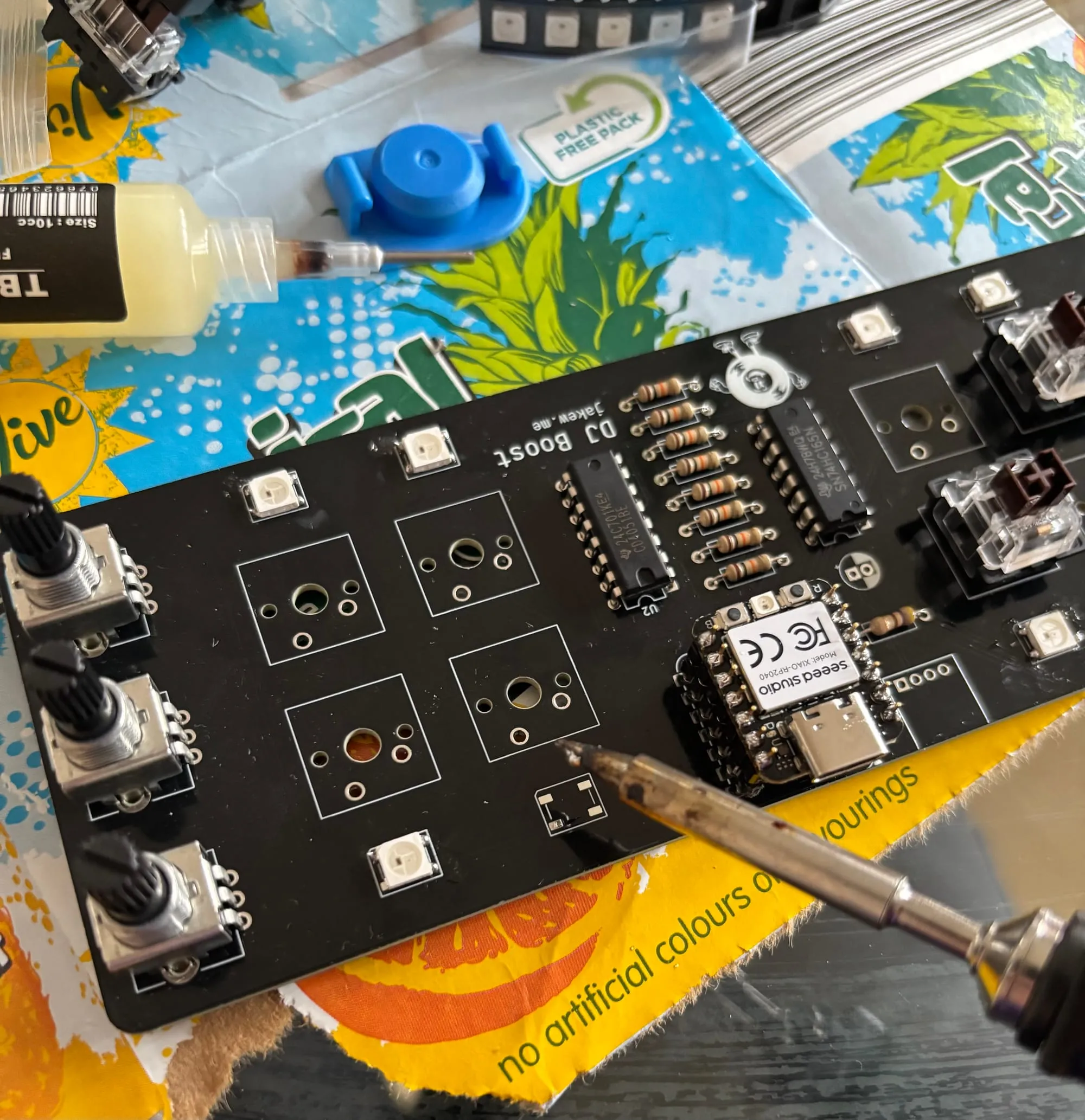
I found it difficult to find a grove connector that was a reasonable price, plus I didn't really have a use for one yet, so I left that part off. Along with the smoothing capacitor, which I thought I would add later if I had any issues.
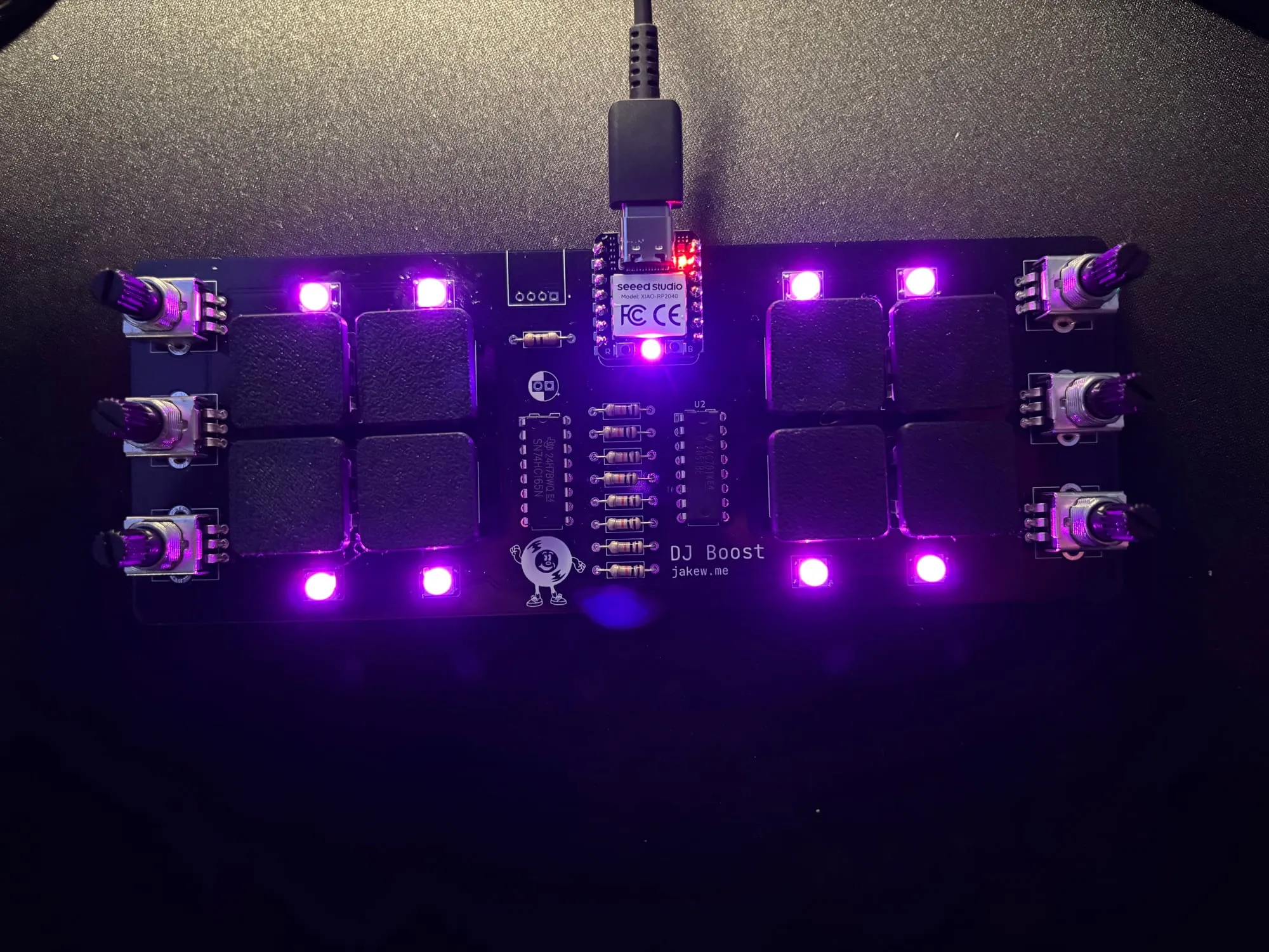
Testing
The potentiometers were a tight fit, so they made a decent enough electrical connection without having to solder them. For the switches I could short the two contacts on the board with tweezers to give them a test.
I wrote some very basic code to check everything was working okay before I soldered everything in. Luckily there was no issues. I used CircuitPython for the testing, as it's super easy to throw together some code, plus they have some great built-in libraries for this use case, specifically a keypad matrix library that worked with the shift register to read the button inputs easily.
import analogio
import board
import digitalio
import keypad
import neopixel

# setup pins for the potentiometer multiplexer
pots_a = digitalio.DigitalInOut(board.A3)
pots_a.direction = digitalio.Direction.OUTPUT
pots_b = digitalio.DigitalInOut(board.A2)
pots_b.direction = digitalio.Direction.OUTPUT
pots_c = digitalio.DigitalInOut(board.A1)
pots_c.direction = digitalio.Direction.OUTPUT
# this is an array of our three input pins for the multiplexer
pots_s = [pots_a, pots_b, pots_c]
# this is the pin for reading the multiplexer value
pots_z = analogio.AnalogIn(board.A0)

# fancy built-in library for reading the shift register button presses
k = keypad.ShiftRegisterKeys(
    clock=board.D9,
    data=board.D7,
    latch=board.D10,
    key_count=8,
    value_when_pressed=True,
)

# another fancy built-in library for controlling the LEDs
pixels = neopixel.NeoPixel(board.D6, 8)


# this function helps select a specific potentiometer by converting the `p` argument to binary that is sent to the pins
def select_pot_pin(p: int, pins: list[digitalio.DigitalInOut]):
    for i in range(len(pins)):
        pins[i].value = (p >> i) & 1


# example code for setting colours on the LEDs
for i in range(8):
    pixels[i] = (10, 10, 10)
pixels.show()


while True:
    # example code for reading the potentiometer values
    for i in range(8):
        select_pot_pin(i, pots_s)
        print(f"{pots_z.value:06}  ", end="")
    print()

    # example code for reading button events
    event = k.events.get()
    if event:
        print(event)

    sleep(0.25)
Software
Once I was happy everything was working, I wrote a bit of code to get it to work in my DJ software. Unfortunately, my software doesn't have any custom MIDI support, which is absolutely what I would try to use. That would be as simple as sending MIDI codes from the microcontroller using CircuitPython's usb_midi package.
I'm hoping to have a try with the MIDI approach in the future. However, for now, I had to go for a bit of a hacky approach using a Python program running on my computer. This uses pyautogui to adjust UI elements in the software using mouse and keyboard shortcuts. I did a quick proof-of-concept where I found the coordinates of the effect knob on screen, then the script will click and adjust the control up and down.
- I used
pyautogui.position()to get the current position of the mouse, then hovered over the knob I wanted to control, then noted the position. - Then it's as easy as using
pyautogui.moveTo(x, y)to move the mouse cursor to that position on screen, thenpyautogui.dragTo(x, y, button='left')to click and drag the control. - For the buttons, I could send keyboard shortcuts using pyautogui and map them to the buttons I wanted to in my DJ software.
- The microcontroller had some basic code to send the input states (potentiometer readings and button presses) over USB serial to my computer where the local program listened then changed controls and performed keypresses as appropriate.
I'm hoping to work on this a little more over the coming weeks to get it to be more reliable, but as it is now, it works okay but is a little janky and can break easily, so I won't share where I've got to with the code, but will hopefully revisit this in another post.
I like the idea of trying out embedded Rust for the next iteration of the code. I really enjoy working with Rust and all the features I need are pretty well supported at this point.
Giving it a go
With the slightly janky code written up, it was time to give it a proper test. You can see a short demo video below. Unfortunately no music here, I don't want to get into any trouble!
The video isn't in perfect sync, but as you can see, the buttons are pretty responsive - immediately turning on and off the effects. However, the potentiometers need to actually move the mouse, which takes a little time. I also had to slow down the mouse movements because the software wasn't picking it up when it was any faster. Most of these effects I think I'd want to have pretty fast control over, so the potentiometers are definitely not as responsive as I would like, especially when turned from one extreme to the other. Luckily this is all just a software problem which can be iterated upon to make gradual improvements.
Wrapping Up
Although this has been my journey making a 'DJ'-type macropad, this could absolutely work for anything else, maybe a video editor with too many keyboard shortcuts or needing fine control over scrubbing over a timeline? Maybe add an ESP32 instead of an RP2040 and have it as an internet-connected home automation shortcut hub. You could even use the open-source project, deej, which lets you make a physical volume mixer, useful if you're into gaming. The possibilities are pretty endless and being able to create your own thing that fits your needs exactly is pretty awesome.
Let me know if you make anything cool based on this, I'd love to see it! And make sure to keep an eye out as there may be follow up posts to this project in the future.