Tildagon Prototype Hexpansion Docs
The prototype hexpansion is an expansion module for the Tildagon EMF Camp badge. It is compatible with the badges for from 2024, 2026 and hopefully future badges too. You can see more information on hexpansions on the badge docs.
Summary
The board is designed and manufactured with the guidance from the badge docs, like 1mm thickness, ENIG finish, etc…
When looking at the bottom side of the board:
- The top row of pads provides 3.3v power.
- The bottom row of pins is ground.
- The pads inside the rectangle are the pins exposed by the badge connector. The text to the side shows what each is connected to (for example, LSE is the second pad down on the left side).
Projects
If you’ve made something cool with your prototype expansion, I’d love to add it here! Contact me
Usage
To add components to the board, solder it through any of the unconnected pins on the board. Then solder small wires to power, ground or data pads. You will need to probably have the components on the top side of the board to avoid them hitting the badge.
I also have a breakout I have soldered a header on which lets me use a breadboard with my badge.
There is a Breadboard Tester app, made by Naomi Pentrel, which is great for initial prototyping and lets you turn on and off each of the low and high-speed pins.
For basic testing, you can install mpremote to get a REPL on your badge. Run the mpremote command on it’s own to connect to the badge, then you can run Python on the badge without making an app.
There is more information on writing code to control hexpansions in the docs here.
Examples
Basic
from system.hexpansion.config import *

# get the pin configuration for the 1st expansion slot
conf = HexpansionConfig(1)
# configure the 1st high-speed pin as an output
conf.pin[0].init(conf.pin[0].OUT)

# read the current state
conf.pin[0].value()
# turn on the pin
conf.pin[0].value(1)
# turn off the pin
conf.pin[1].value(0)
NeoPixel
I have connected NeoPixel (or WS2812) LEDs to an expansion by connecting the data pin to HSF (or high-speed 1). Assuming the expansion is in the 4th slot on the badge, this code lights the first NeoPixel to white.
from system.hexpansion.config import *
import neopixel

# get the pin configuration for the 4th expansion slot
conf = HexpansionConfig(4)
# create a new neopixel driver for the 1st high-speed pin on the expansion
np = neopixel.NeoPixel(conf.pin[0], 1)

# set the pixel to white
np[0] = (255, 255, 255)
# apply the changes
np.write()
This is a basic example, but you could improve this by detecting which port the expansion is in rather than hard-coding the 4th slot.
Connections
The board breaks out all available GPIO available from the expansion connector. This being 9 GPIO pins (5 low-speed and 4 high-speed), I2C, detect and of course power.
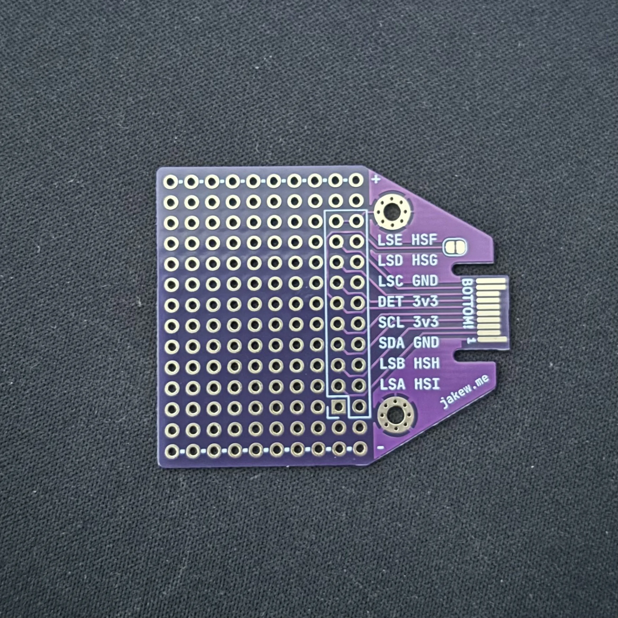
When looking at the bottom side of the board, the top row of pads are a 3.3v power rail, and the bottom row of pads are a ground rail.
Within the silkscreen box on the right side (nearest to the connector) are the pins available from the badge:
| Left column | Right column |
|---|---|
| Ground | Ground |
| Low-speed 5 (LSE) | High-speed 1 (HSF) |
| Low-speed 4 (LSD) | High-speed 2 (HSG) |
| Low-speed 3 (LSC) | Ground (GND) |
| Detect (DET, see below) | 3.3v (3v3) |
| I2C SCL | 3.3v (3v3) |
| I2C SDA | Ground (GND) |
| Low-speed 2 (LSB) | High-speed 3 (HSH) |
| Low-speed 1 (LSA) | High-speed 4 (HSI) |
| Unconnected (square pad) | Unconnected |
On the badge, the low-speed pins are connected via GPIO expanders so cannot switch as fast as the high-speed pins. If you are connecting anything sensitive to this, for example sensors, you want to try and use the high-speed pins if you can.
The rest of the pads are unconnected.
Detect Pin
The Detect pin lets the Tildagon know that a hexpansion has been inserted or removed. It also controls power to the hexpansion. […]
On the prototype board, the detect pin is wired to ground so that the badge can detect that the expansion has been plugged in, and provides power to it. For most cases, this is how you’ll want it connected.
If you want control over the detect pin, locate the jumper pad to the right of the silkscreen HSF & HSG text where the 2 pads are in a rounded rectangle.
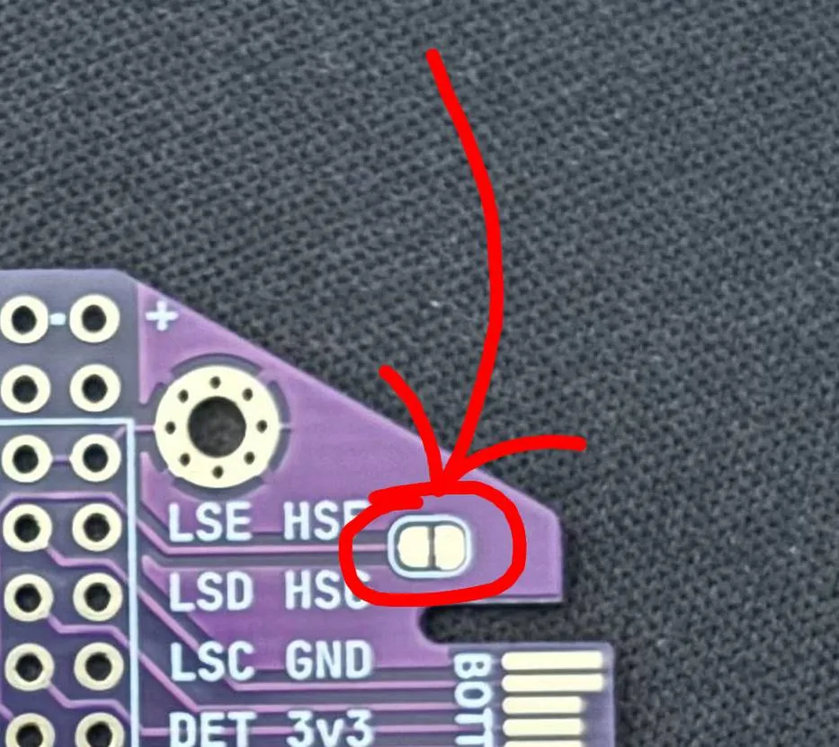
Cutting the trace between the pads will disconnect the detect pin from ground and give manual control. You can cut the trace with an Exacto-style knife or other sharp blade - it may take multiple passes.
To undo this, simply bridge the pads with solder where the trace was cut which will restore the original connection.
Specifications
- 10x14 grid of pads
- 20 pads for the breakout
- 10 for the 3v3 rail
- 10 for the ground rail
- 110 unconnected
- 1mm thickness
- ENIG finish (lead-free)
- On boards sold after May 2026, the edge connector has a bevelled edge to improve insertion.