In my last post, I worked on the PCB and design for my cyberdeck project. As a quick recap, this is a project to make a handheld computer which can be used for mini apps like a pomodoro timer, note taking, communicating and other stuff.
For this project, PCBWay kindly offered their PCB prototyping services which I'm very grateful for. Their pricing is very competitive and I found it quick and easy to get my designs uploaded with their KiCad plugin.
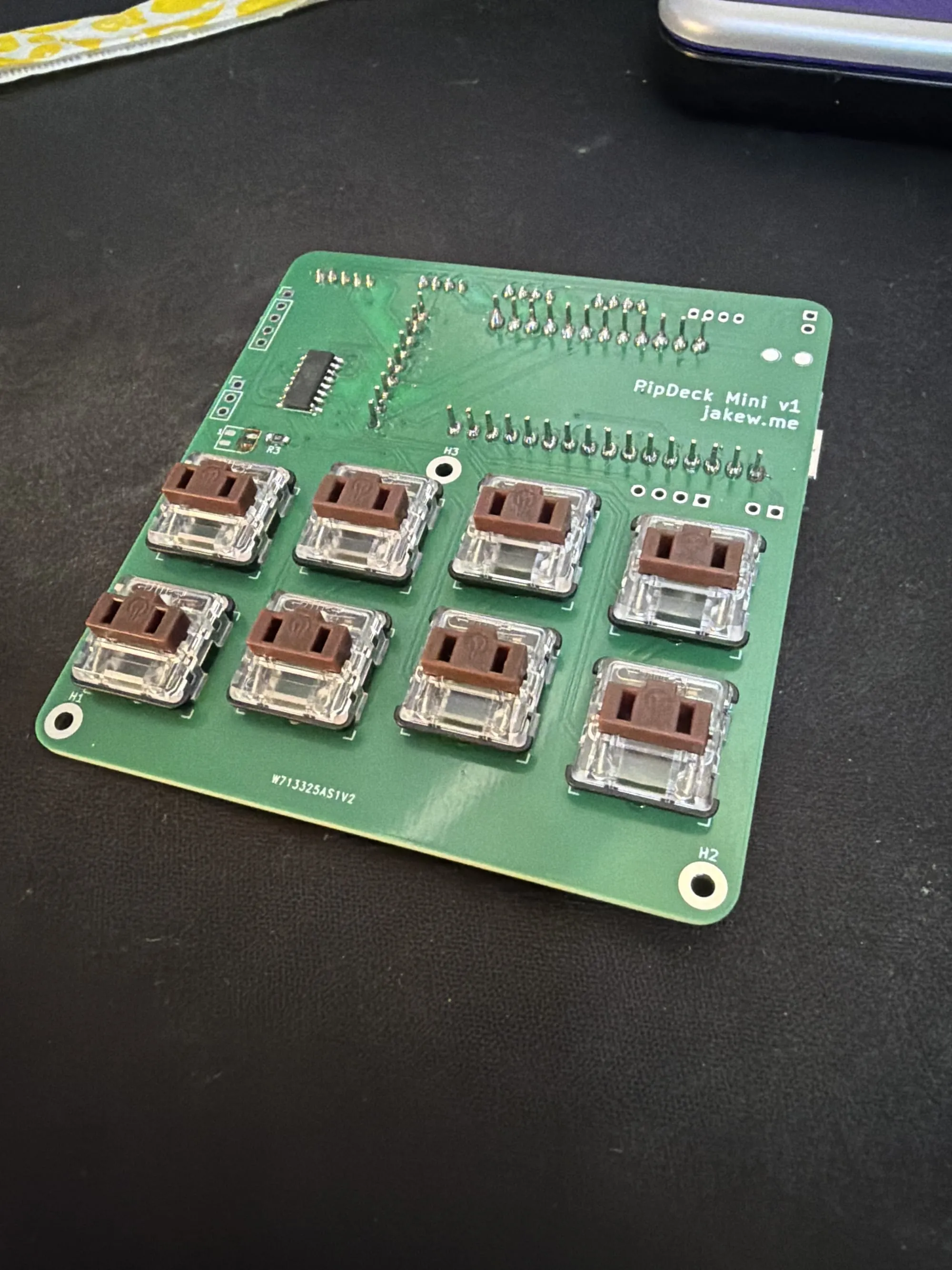
The finished boards arrived in around two weeks after ordering with their most economical shipping option. As always, the boards are fantastic quality, feel sturdy and are just a joy to solder on.
You may notice the silkscreen name on the board, "PipDeck Mini", which I feel works well with the ESP32 brain - it's small and not very powerful. If I ever make a bigger version, perhaps with a Pi Zero or something else, I can hopefully keep the same name.
Assembly
I started off with the smallest components first. These were the surface mount pull-down resistors for the keyboard switches. As I'm using a shift register for the keyboard, these resistors are needed, however if you were hooking the switches up directly to GPIO pins, you could omit these and use the micro-controller's built-in pull-downs.
I'm using a probably not-so-safe cereal box on my table, just to catch any rogue solder blobs. I should probably grab something better!
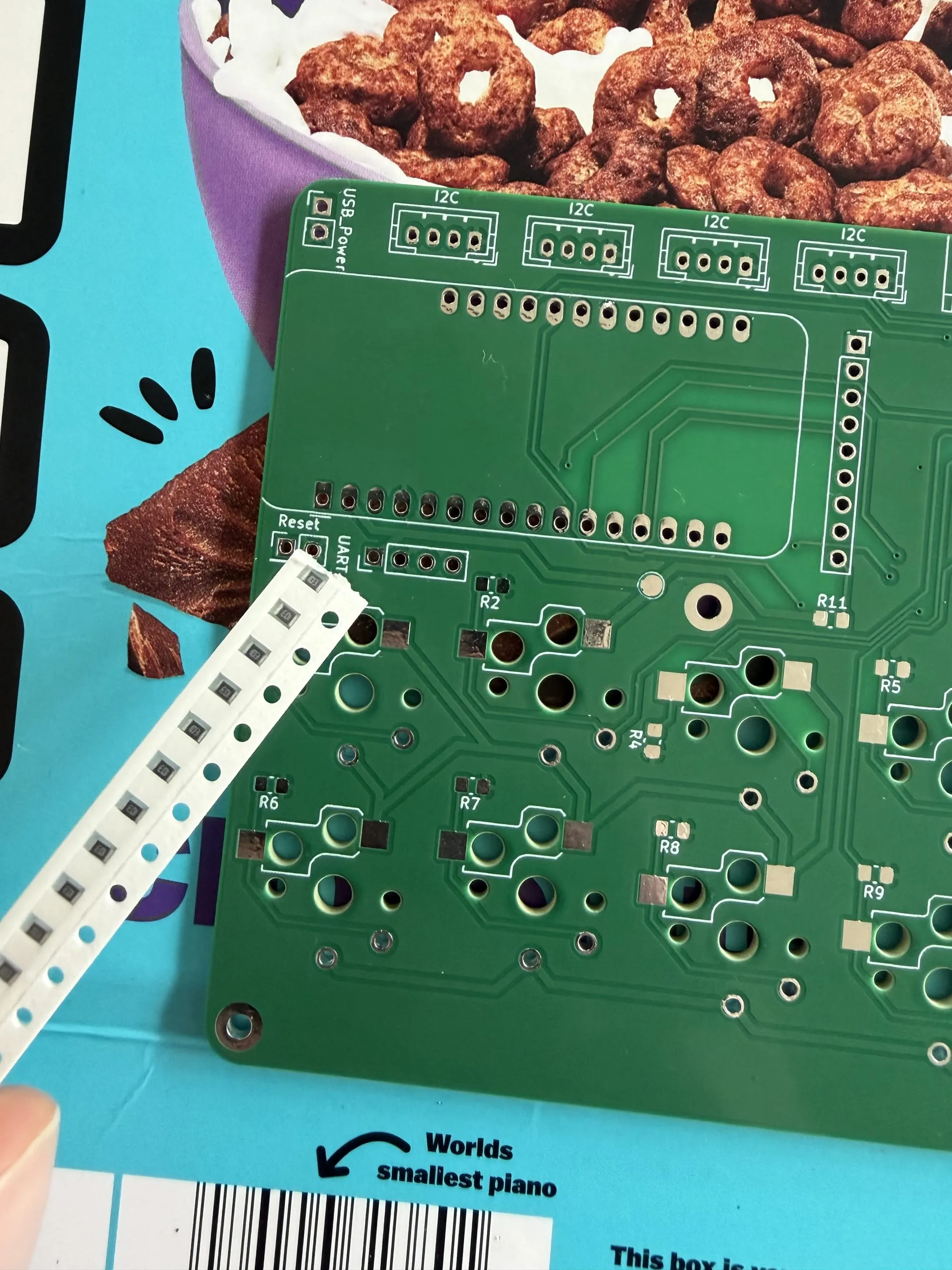
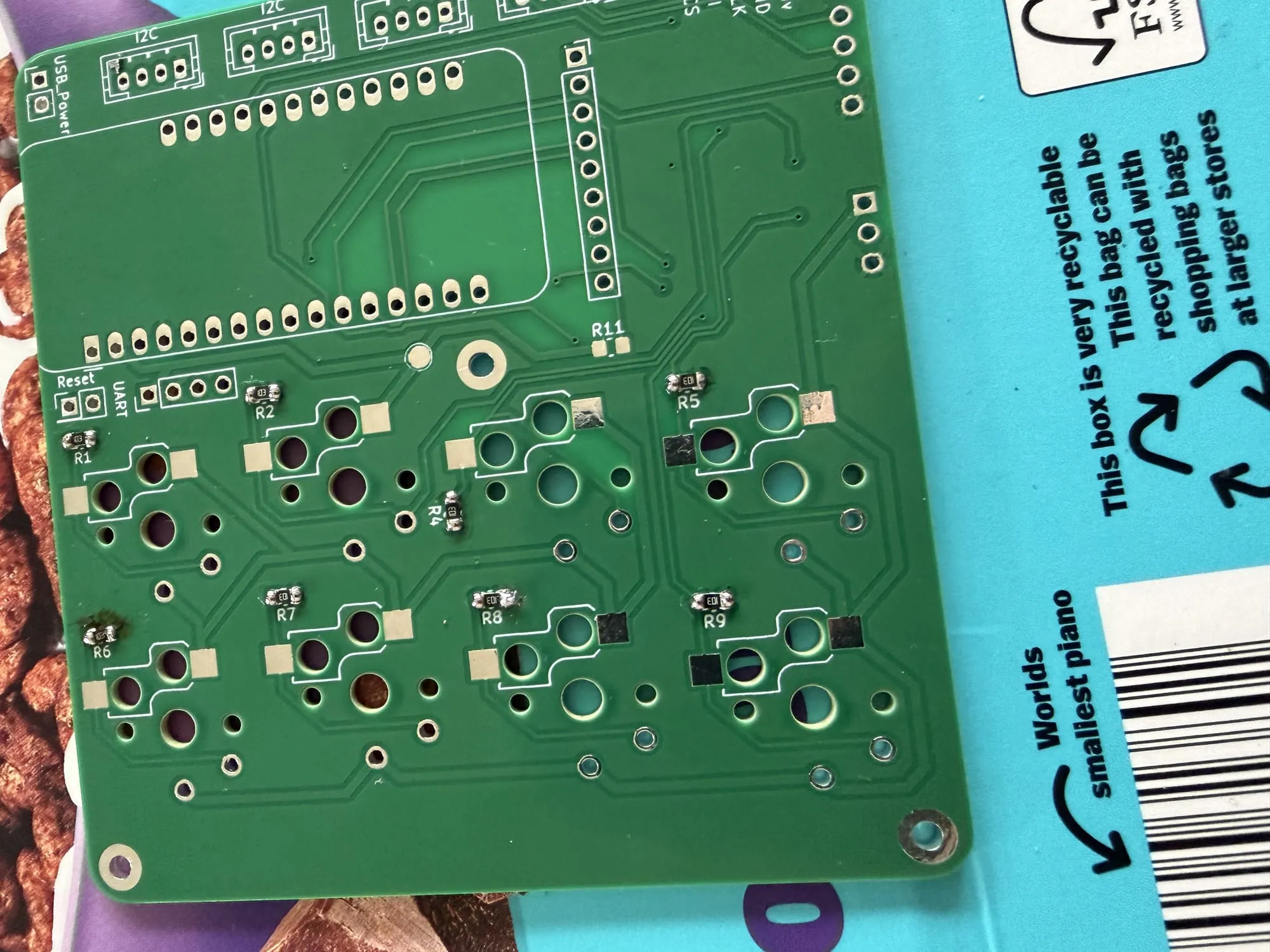
With the resistors soldered on, I next added the hot-swap keyboard switch sockets. Although they could again be soldered on directly (and the footprint I used supports using the sockets or directly soldering), it makes it easy to swap out broken switches, or swap them for different feeling switches later on.
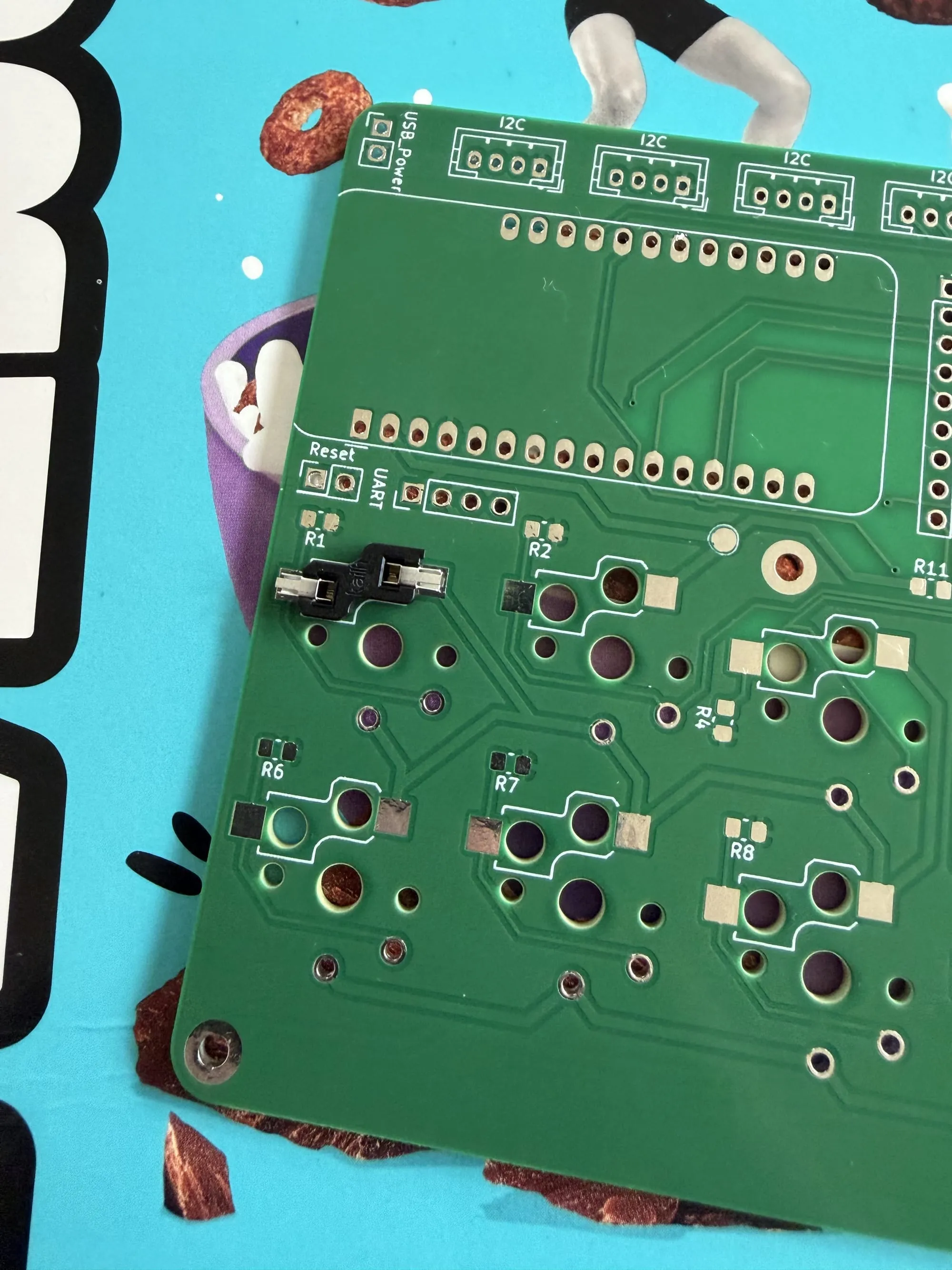
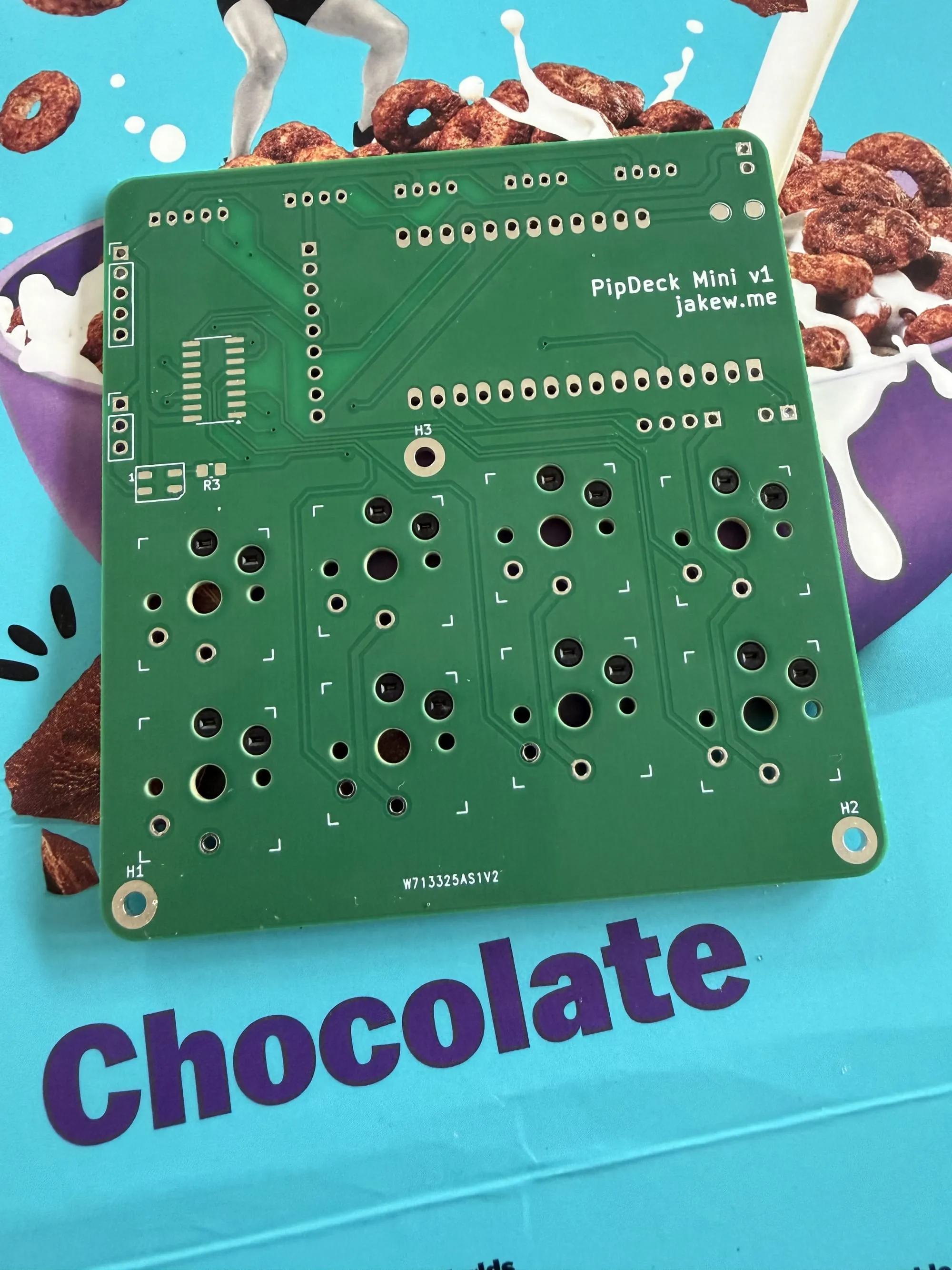
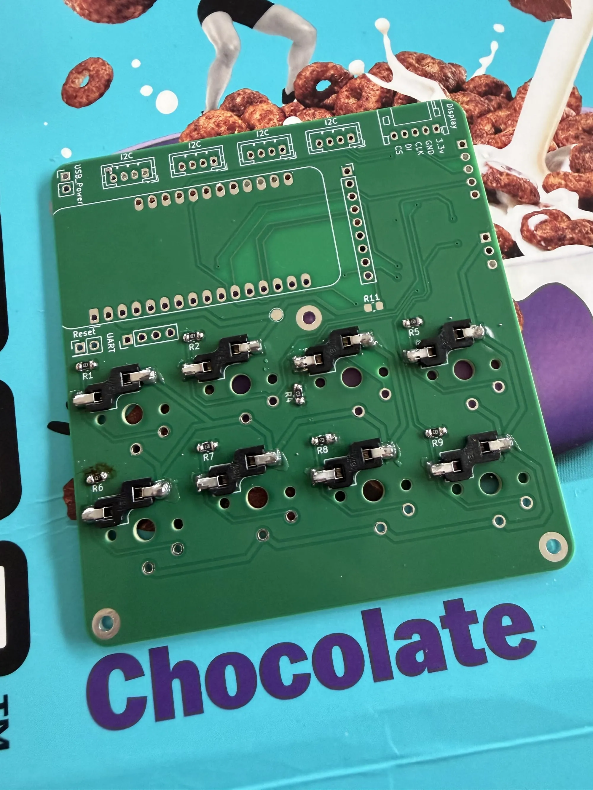
I was a little worried about how well the switches would hold with just the hot-swap sockets since on another project, I found them to be a little wobbly. However, they hold in pretty strong, even without a case for them to clip into.
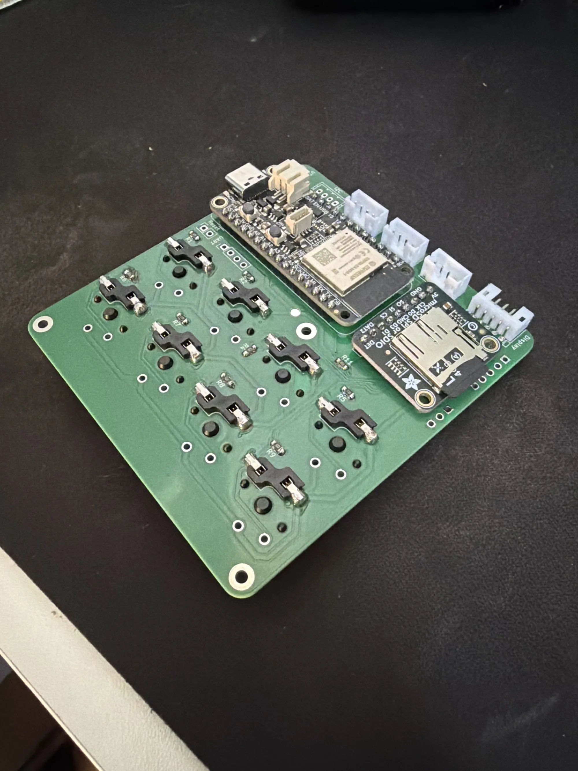
With the smaller components soldered on, I finished up by adding on the shift register chip, the Adafruit ESP32-S3 Feather micro-controller, the SD card breakout, and a few of the JST connectors for I2C and display. I would have loved to put the micro-controller and breakout board into pin headers, but unfortunately that takes up quite a lot of vertical room and I'm wanting this project to be low profile. I felt like this was alright given they're not too expensive.
I made a little mistake here, and had to leave out the leftmost connector since it would have been where the battery plugs into the micro-controller - luckily there's still plenty of connectors so it doesn't matter.
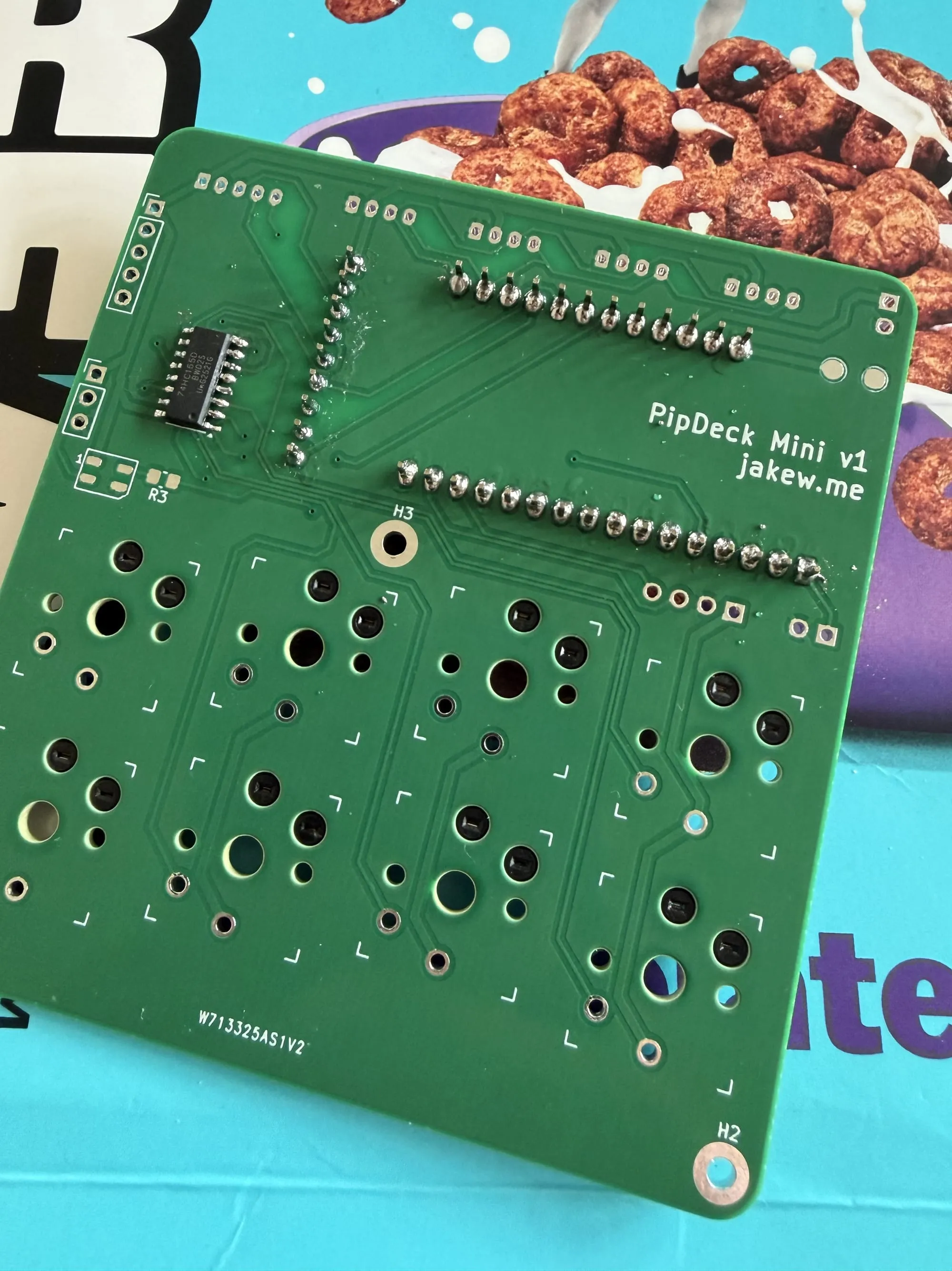
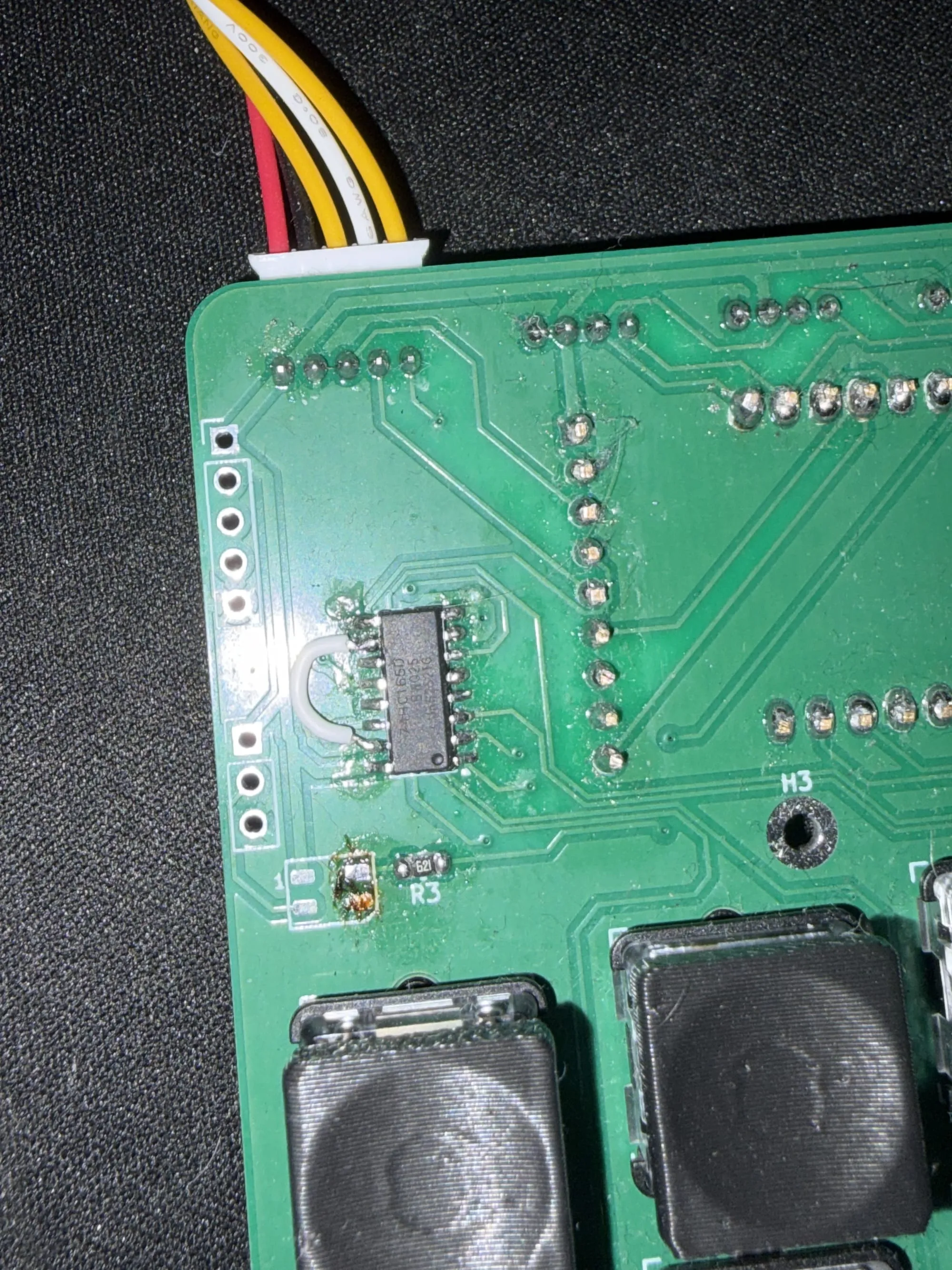
Unfortunately, I had another mistake with the only part I didn't try on a breadboard - the shift register. I forgot to ground one of the pins so needed to add a jumper wire between two of the pins to fix things. Without the jumper there was some funkiness with the inputs and other SPI devices.
With that, the assembly is complete! The low profile brown switches push in and get gripped by the PCB pretty well, so they aren't going to fall out. I soldered on a connector for the display and got that plugged in too, but you'll have to see that later on.
I didn't check the size of the RGB LED I added to the design, and didn't have the right part on hand, only a bigger size, so I've left that out for now.
Software
While I was designing the PCB and waiting for them to arrive, I got started on the software side of the project.
The main programming languages for an ESP32 project I'd tend to gravitate towards are Python and C. For Python, there's stripped down versions of "normal" Python which are designed for micro-controllers - the well established MicroPython, and Adafruit's more friendly CircuitPython. I find Python great for prototyping, but I don't like the lack of typed variables and although the type annotations are fine and work with MicroPython, I would much rather use something else for a more complex project like this. C is also great and highly performant, but I'm not very familiar with it, and there's a lot of ways to shoot yourself in the foot, especially for a project like this where there might eventually be lots of moving parts in the code.
Although it's a little newer and there's not a ton of libraries available, I thought I'd try embedded Rust out for this. I really enjoy writing it, the memory safety features are great and it's still highly performant. I've only done one other project with embedded Rust before, but I had to port it over to C in the end, just because of a Bluetooth library I wanted to use, and didn't fancy implementing a whole Bluetooth stack in Rust. However, for this project, hopefully everything I need is there. Also as a bonus, it's pretty easy to run on my own computer for development.
Architecture
For the software, I started development on my computer, but also want to be able to run the same OS on other devices - perhaps if I make a second revision of the hardware. Essentially, I didn't want to write all the code for the specific hardware I've put in my project, I wanted it to be abstract and work for anything, as long as a little code was written to bridge the gap.
I wrote an "OS core" which pretty much contains everything - including apps, a basic scheduler and other parts. Most importantly, the core defines abstract classes (or traits for Rust speak) for any peripherals like the display, keyboard, battery, LEDs, network and storage.
The simulator, which I created next, just implements these abstract drivers for the hardware - which in this case is a simple GUI application (using embedded-graphics-simulator). The core keeps track of the display buffer for drawing to, but sends that buffer to the specific display driver which handles the actual drawing to the screen. Similarly the OS asks the keyboard driver if there are any inputs available, or does network or storage operations using standard function calls into those drivers.
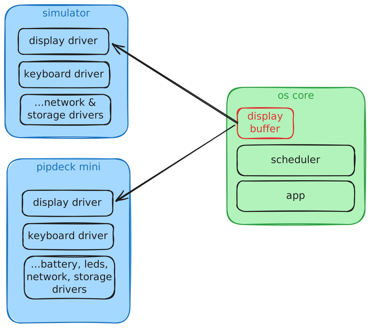
With this architecture, it let me develop quickly and easily on my computer without any physical hardware, and even with the hardware, it lets me quickly test things out without having to flash the micro-controller for each change.
For peripherals like the battery, the simulator can just give a fake value, and for the LED controller it can just print out what value would be set, or do nothing at all.
Once I had my hardware sorted, it was a case of just making a new embedded Rust project, then creating drivers for all my hardware. If I wanted to port this to a new device, I can just do the same again, and any changes to the core should just work after re-building for the device.
I did run into a couple of quirks when initially getting the code running on the micro-controller though. The first being the display driver I was using which I had to make some changes to so it would use heap memory, rather than stack. I also had to increase the stack size, I think after adding in WiFi stuff as that used up a lot.
This is a bit of a simplification, but if you're interested, the code is open-source! Feel free to check it out.
 jakew
jakew
The OS side is still in pretty early stages, and I've already had to make some tweaks to make the code run faster on the physical device with it's much less powerful CPU compared to my computer, and memory constraints too. I'm hoping this will become a fun long-running project though.
Scripting Apps
One thing I also had from my original requirements is that it's easy to write apps for. I'm fine with writing apps in Rust, but it means I have to recompile the Rust project each time I make changes to an app, which isn't super ideal. And also Rust isn't the best language for quickly throwing something together like Python would be.
I started exploring a few ways of adding a scripting layer to the OS which would allow app scripts to be loaded dynamically from the SD card and executed. Now obviously these scripted apps wouldn't be as performant as Rust, so I'd have a mixture of both baked-in Rust apps, and script apps also.
I found a few options:
- Lua (
mlua/piccolo) - these are both Lua runtimes which run in Rust.piccolois written in pure Rust so in theory would be a little smaller on resource usage on an embedded project, however I found it didn't have support for Lua tables which I thought would be quite useful to have.mluaon the other hand links to the C Lua runtime so it's more heavyweight but has support for much more of the Lua language. - Rhai - a pure Rust scripting language which has a Rust-like syntax. I really liked this one, but it's a new language to learn and it doesn't have the IDE or community support like Lua does.
- Starlark - a Python-like language used in Bazel build files and has a few features that make it ideal for embedded applications, but it's mainly designed for configuration rather than general scripting.
- Wren - a small scripting language designed specifically for embedding, but similarly to
mluait uses a C library under the hood. - JavaScript (
boa/quickjs) -boais a pure Rust JS engine andquickjsagain uses a C library under the hood.
I settled on trying mlua just because of the IDE integration and community support available - it's been around for much longer than some of the others. However, Rhai was definitely my second choice, and I might re-visit in the future.
With Lua taking up a lot more RAM and flash space, I put it behind a feature flag so it can be added or removed easily during compile time.
I'm still working on this and there's a lot of work adding Lua function calls to Rust methods underneath - for example interacting with the networking or drawing UI elements. At the time of writing, I've got a basic Lua app running in my simulator. However, the use of a C library under the hood might make it challenging to compile for the micro-controller, in which case I may fall back to Rhai.
Wrapping Up
With all that, I'm going to wrap up part 2 of this adventure. In the video below, you can see where I'm currently up to, with a working device and the OS running on it.
I've been rather busy over the past few months so not had much chance to continue on the project, but my next steps are to improve the software and try to design a 3D printed case. The case will be challenging since I've not 3D modeled anything as complex as this before! Stay tuned for the next post.