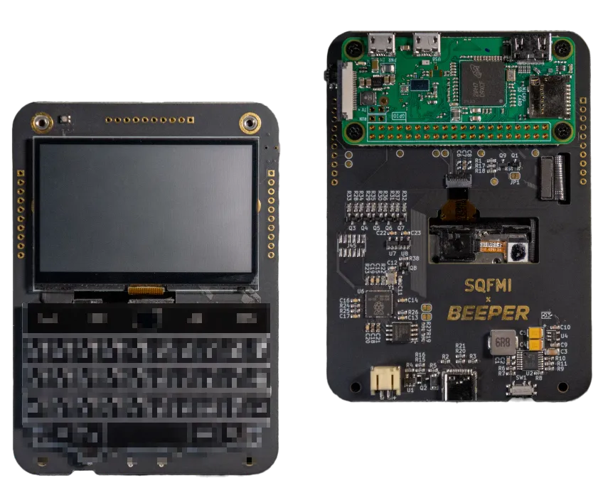
For a while now, I've wanted to get a "cyberdeck" or Raspberry Pi handheld. One of the cleanest examples I've seen is the "Beepy" which has the keyboard from a Blackberry phone, a lovely SHARP Memory Display (a monochrome LCD which has some e-ink qualities) and a Raspberry Pi Zero strapped to the back. Sadly there's a waitlist for these and I don't get the impression they're mass produced, so probably quite difficult to get hold of one.
Some other inspiration I had, which I sadly can't find the link for now, was a Raspberry Pi handheld with an ARTSEY.IO layout keyboard. It's a strange keyboard layout which only uses 2x4 keys. This means you can get a keyboard you can type on reasonably quickly once you've practiced, but with regular size keyboard keys in a small form factor.
On Reddit, there's an endless supply of cyberdeck designs on r/cyberdeck which were amazing for inspiration as well. I'd say the majority of them are based around Raspberry Pis but sometimes more powerful computers also.
The Plan
Now that I'm more comfortable making PCBs, I thought it would be an amazing chance to try and make my own, exactly with the features I wanted.
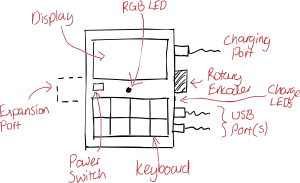
To get started, I made a small list of things I wanted my cyberdeck to do, and be used for. A few requirements I came up with were:
- Fast to turn on - I don't want to go to use the thing and it take minutes to turn on. I'd probably just end up using my phone or laptop instead!
- Some sort of keyboard - I want to be able to type on it relatively easily, so no on-screen keyboard with arrow keys for navigation.
- Expansion port - I may want to add more features to it down the line, like perhaps being able to talk on a mesh network like Meshtastic or maybe adding sensors or plugging into something for monitoring serial communications.
- Battery powered - I don't want to be next to the wall to use it, it needs to work out and about on battery power, and last a reasonable amount of time.
- Small & pocketable - I want to be able to carry this around, maybe in a larger pocket, but the aim is to be about the size of a phone.
- Things I'd like to be able to do with it:
- Light communication - perhaps over LoRa/Meshtastic
- Serial monitoring
- Note taking - perhaps with Obsidian integration
- AI assistant chat?
With these requirements in mind, I thought a Raspberry Pi Zero would be the choice - it's a full fat Linux environment so it can run any programming language, and is able to connect to external monitors, or a full sized keyboard could be plugged into it.
I also chose a few other components that I wanted too:
- A LiPo battery, fuel gauge (for reading battery charge) and LiPo charging circuit (the LiPo Amigo Pro). It would have been a lot cleaner to build my own battery charging circuit here, but I felt a lot safer using existing breakouts that I knew would be safe. One mistake on my own LiPo charging circuit design could spell disaster! The fuel gauge would communicate to the Pi over I2C.
- For the keyboard, I settled on the 8-key ARTSEYIO layout mentioned above. It's got a steep learning curve, but once you've learnt you can type any letter out on it with chords. For simplicity, I added a RP2040 microcontroller to handle the inputs from this which could run QMK. There'd also be a rotary encoder which allows me to scroll menus and things.
- I was initially undecided on a display, but most of them seemed to use SPI for communication. SPI is used for both colour LCD and the SHARP memory display I mentioned above.

After looking into components, I found that the Raspberry Pi Zero may not be such a great choice. A lot of space would have been used up for all the battery components. There was also a big question around safely turning the Pi on and off - the LiPo circuit had a power button, but it's not able to safely shut down the Pi, it'd be like pulling the power from it which could result in file corruption. I was thinking that having a mostly read-only filesystem might help with this, but it's still not ideal. And I couldn't find any other LiPo charging circuit breakouts that would have been suitable for safely powering off a Pi.
Another problem I had with this design, was the speed of powering on from cold. I tried using a very lightweight Alpine Linux install on a Pi, and making as many tweaks as I could to improve boot up times, but it still took a good 30 seconds to boot up. That's fine, but again not ideal.
In the end, I decided to switch to an ESP32-S3 for the brains of the project. I found a board with a built-in LiPo charging circuit and battery meter, which reduces the space needed for the breakout boards, plus it wouldn't need the USB hub I was planning to add. Obviously this comes at the price of not being as powerful, but I felt like it was worth doing. I have a fantastic EMF Tildagon badge which is also powered by an ESP32-S3 and it's honestly pretty capable for most small tasks including calling APIs, rendering graphics and so on... I decided to also add in a microSD card adapter for extra storage as the microcontroller is limited to ~4MB.
Although it was a lot more expensive than a colour TFT display, I did go for the SHARP memory display in the end for the project. It's a beautiful sharp display, unfortunately with no backlight, but I felt it would give the project a very unique look. Not to mention it's also a lot less power hungry than a conventional TFT display.
Designing the PCB
With a better plan, I got to work on designing the PCB. Unlike a lot of my other PCB projects, I spent probably a month or so going back and refining the design multiple times. When I got to the point of wanting to call it finished and looking for parts, I did find some problems with availability and had to swap out or remove parts. For example, with the rotary encoder I couldn't find one that mounted the way I wanted and also wasn't insanely expensive - so I decided the keyboard would be fine and dropped it from the design.
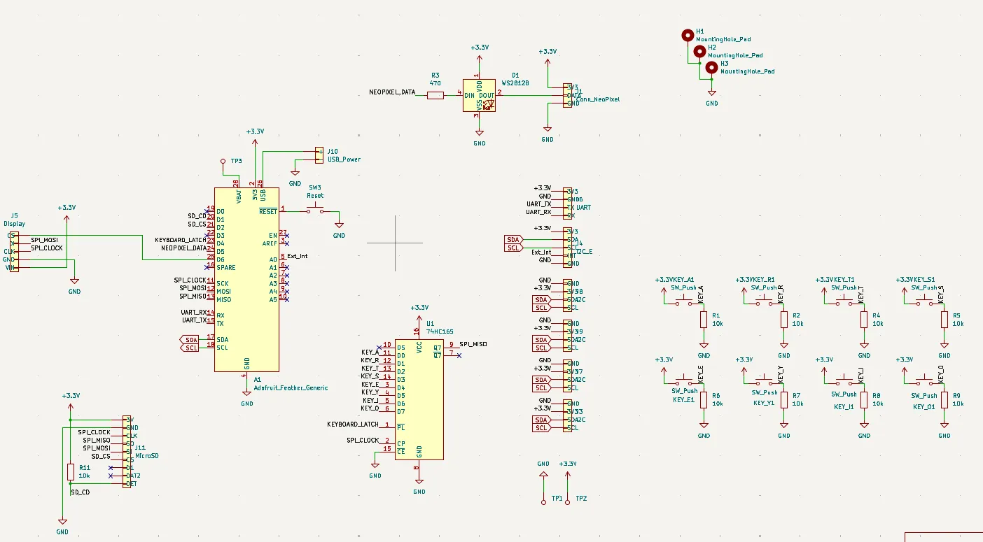
The schematic for the design was pretty straight forward, with the microcontroller being the brains of the project, and just connecting up everything to that. The display and microSD breakout are connected with headers, with the microSD breakout needing a pull-up resistor for the card detect pin. You'll also notice a bunch of I2C ports which I wanted to add in for future expansions - one of them has the pinout for a Pimoroni breakout garden connector which means I can very easily design expansions later that plug straight into a connector, the rest being Grove connectors for more permanent additions.
With the few GPIO pins remaining, the keyboard needed to be hooked up with a 74HC165 shift register which means we can read the 8 inputs on the keyboard with the SPI bus (2 data pins) on the microcontroller. Finally there's a Neopixel and header for flair!
With this project, I was also trying to make the PCB as compact as possible. The keyboard was the limiting factor here as it had to be laid out in a 4x2 grid. However all the other components I tried to squish up at the top, hopefully under where the display will be mounted.
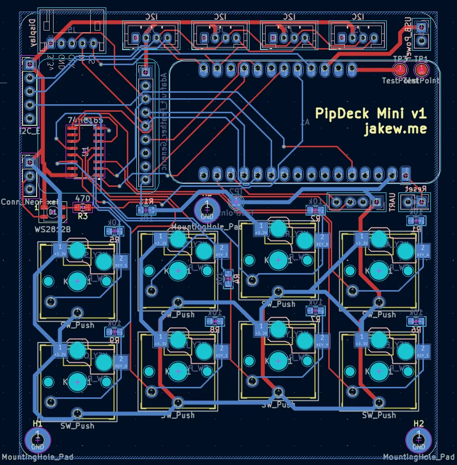
With the board designed, and some basic prototypes on breadboards complete, I sent the design off to PCBWay to get it ordered. With their KiCad plugin installed, I was able to get it uploaded with literally 1 click which is awesome - no faffing with the export settings.
In the next post, I'll be checking out the PCBs, soldering up everything, and talking a little about the initial OS code I've been working on.
If you'd like to check out the KiCad project for this yourself, the files are available here, but I'd urge you to have a go at making your own that fits your own use cases! That's the amazing thing about the cyberdeck community.